...
- Fergo ASC and VR3 Documentation Break Down → This is an non-negotiable must read for all members, as it specifically lays out the guidelines and regulations we must follow to ensure we meet ASC and FSGP standards.
- Calvin Guo - 2021 Exit Summary → This is an exit summary of a formal Solar Frame lead. This contains some good information when starting out on the frame subsystem. (Disclaimer: I touch on many of the same topics, but Calvin gives a different perspective on some things, so it's worth a read)
- General Roll Cage and Automotive Structure Guides → These articles range anywhere from FSAE to professional racing sectors, in which describe the purpose of a roll cage, building strategies, and tips on what to avoid and how to make structures more efficient.
- The entire “To Win” series by Carroll Smith is a great series written on motorsport racing and race car development as a whole. These are great reads as a whole if you like cars, motorsport, and automotive engineering in general.
...
Necessary
...
Fundamental Knowledge
To build an effective frame, one must be knowledgeable in the realms of primarily Solids, Statics, and Materials, and Solids, as well as knowing the optimal ways to build structures as a whole.
DISCLAIMER: I never completed any of these classes upon first drafting this work, so here’s the quick and dirty, cut-and-dry, condensed version of what you will need to know but these are continuously updated as a I venture into the topics in class, on my own, and as I encounter them in LHRS as a whole. 👍
Statics
Start here → Statics Lecture.pdf
...
- Axial forces (forces parallel to the center axis of the tube) can cause compression or tension in a tube, which can essentially be broken down into squeezing or stretching a tube
- Too much of either tension or compression can lead to either buckling or plastic deformation or buckling (see picture below/will talk about later)
- Tubes are the most resistant to axial forces as compared to shear forces or bending moments
- Buckling is more common in longer, less stiff tubes (I.e. shorter, stiffer tubing → less chance of buckling)
...
Supports will come in later when you take Statics/are introduced to Ansys (FEA).
- All that matters is that different types of supports resist Supports assume infinite stiffness in specific degrees of freedom. Some supports (like fixed) have reactionary forces and moments in all DOF, some like (roller and pinned) have reactionary forces and moments in only specific DOF
- All that matters is that different types of supports resist different types of forces/moments, which you can use to solve/isolate forces and understand the reactions happening in a system
Materials
Start here → Materials Lecture.pdf
Every material is made up of a Two Force Members
- A two force member in our case would be a tube with forces only acting in two locations, with the forces being equal opposite and colinear.

Truss Structures
- In our case, a truss structure is structure made to take high loads while utilizing 2 force members, thus taking high axial loads, while minimizing bending loads.
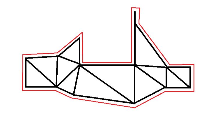
Each of the distinct areas of the above frame feature their own truss structures with either compression or tension loaded cross-braces.
Materials
Start here → Materials Lecture.pdf
Every material is made up of a crystal structure (crystal defects, a unique organization of atoms, etc.) which leads to materials with unique/different properties (i.e. this is how you get alloys, a mixture of chemical elements with at least one metal)
...
What happens to a tube when a load case is applied?


This is a stress-strain curve. All you need to know is:, one of the most fundamental parts of Solids. The graph has stress on the y-axis, strain on the x-axis
What you need to know is:
- The elastic region is where the material can have stress applied (elastic deformation) and the process is reversible (the material can go back to its original length)
- The elastic line on the graph is linear because the stiffness of material in this region is like a spring (everything in every situation is like a spring from here on out, remember this lmao)
- most materials mimic the processes of a spring when it comes to deformation)
- This is also the same place where Young's Modulus comes into play.
- Young's Modulus is simply just a number that represents the "stiffness" of a material, representing the ratio of stress over strain. This is unique to each and every material.
- Most importantly, higher young's modulus means a more brittle material (less strain/yielding, can withstand more stress, but more prone to fracturing)
- The plastic region is where the material has stress applied (plastic deformation) and the stress overcomes the energy required to rupture bonds, which is an irreversible process
- Two Important important things:Yield Strength and Ultimate Strength
- Yield strength is the maximum stress a material can absorb before plastically deforming
- Ultimate strength is the maximum stress a material can absorb before fracturing (breaking)
- I’ll talk about this later on in the guide when we get to welding, but essentially, just know that we mainly design things around the yield/ultimate strength.
- Lastly, the Factor of Safety, at least in our case is measured with the yield strength of the material, as well as the max von Mises equivalent stress from the given simulation/reaction (the equation is Max eq stress/yield strength) This indicates when a part can fail

Pictured above, is a stress-strain graph showcasing some common materials. From left to right, we go from harder, higher "strength" materials, that lightly yield, to softer materials, lower "strength" materials, that yield more.
- Strength in this case just means a materials ability to take resist breaking when a stress is applied. A stronger material can take more stress before permanently breaking.
Lastly, the Factor of Safety, at least in our case is measured with the yield strength of the material, as well as the max von Mises equivalent stress from the given simulation/reaction (the equation is Max eq stress/yield strength)
- This indicates when a part can fail
- FOS of 1 means the current simulation/reaction will begin to fail at 1 times the max equivalent stress, 2 means the structure begins to fail at 2 times the max equivalent stress, etc.
- FOS of 1 is the absolute bare minimum a structure should have before it is deemed manufacturable, but some parts of the frame must have a 1.1 minimum, due to high safety goals/concerns (although you should always shoot for something >1.6 FOS)
Solids
Start Here → Solids Lecture.pdf
...
There are 4 main types of stresses each tube will encounter. Those include:
- Normal Stress: Stress that acts perpendicular to the cross-section of interest (compression, tension, or rather axial force)]
- Shear Stress: Stress that acts tangential (parallel) to the cross-section of interest (like a cutting force)
- A common application of this is with bearing stress on a bolt, which leads to shearingbolt shearing.
- Torsional Stress: A shear stress that is caused by a moment about the longitudinal axis of the tube (think of a twisting force)
- Bending Stress: (THIS IS THE BAD ONE): Stress caused by a moment that has tension and compressive stress at each end (think of the cantilever beam problem below
- Also, bending stress is related to moment of inertia (you’ll learn this in Physics I hopefully, but it is basically related to a tube’s stiffness/inertia/resistance to movement)


- of the cantilever beam problem below
- Also, bending stress is related to moment of inertia (you’ll learn this in Physics I hopefully, but it is basically related to a tube’s stiffness/inertia/resistance to movement)
- Simple Bending or Pure Bending A beam or a part of it is said to be in a state of pure bending when it bends under the action of uniform/constant bending moment, without any shear force. Alternatively, a portion of a beam is said to be in a state of simple bending or pure bending when the shear force over that portion is zero. In that case, there is no chance of shear stress in the beam. However, the stress that will propagate in the beam as a result will be known as normal stress. Non-uniform bending occurs when shear forces are introduced.
- Above is the formula for bending stress on this cantilever beam. Here, we have bending stress on the left side, with the calculated bending moment times the vertical distance from the neutral axis, all over the moment of inertia from the neutral axis
- What you really need to take from this is not necessarily all the algebra behind bending stress, but rather the things that affect the value itself, which in this case is bending moment, moment of inertia, and vertical distance.
Some Necessary Basic Structural Knowledge
Triangles - Triangles are the most stable simple geometric structure. Without triangulation, squares have no lateral support. Triangulate everything you can. This principle should be applied as much as possible to a chassis or cage design. Every tube should be one leg of a triangle whenever possible. This is especially true with the primary structural tubes.
Bends - Avoid bends if you can. The strength of a roll cage is based on compression and tension within the structure. Bending reduces both no matter where you do it. Some are unavoidable in a design but they should be minimized. A straight line is more rigid than a curved one. However, it's not always practical to have your roll bar tubes run in a straight line. Bending the tube results in a reduction in overall strength. If you have to use a bend, add bracing to compensate for the bends. Bends should never be mid-span, or unsupported. The apex of a bend should be a node point or junction for at least one other tube and gusseted unless several tubes meet at the node.
T-Junctions - T-Junctions are when one tube dead ends into another. This should be avoided whenever possible because the dead-end tube could apply force to the tube it dead-ended into and cause it to bend.

Imagine a force on the middle tube. The axial forces in the middle tubing would cause shear AND bending stresses on the other tube (because the middle tube is perpendicular to the other tube)
Some other useful tidbits
Simple Bending or Pure Bending A beam or a part of it is said to be in a state of pure bending when it bends under the action of uniform/constant bending moment, without any shear force. Alternatively, a portion of a beam is said to be in a state of simple bending or pure bending when the shear force over that portion is zero. In that case, there is no chance of shear stress in the beam. However, the stress that will propagate in the beam as a result will be known as normal stress.tube dead ends into another. This should be avoided whenever possible because the dead-end tube could apply force to the tube it dead-ended into and cause it to bend.
Imagine a force on the middle tube. The axial forces in the middle tubing would cause shear AND bending stresses on the other tube (because the middle tube is perpendicular to the other tube)
...
Design Tips
- Start by utilizing a combination of 2D and 3D sketches (separate the different parts of the frame!!!)
- This helps make the differences in each part of the frame distinct and separate so that errors do not become prevalent if changes need to be made.
...